

Language:
Español
More info:
FAQ
Bibliography
Peperina team
Other kayaks
Links
Kayakers
Products
NOTE: The images on this pages are in PNG (Portable Network Graphics) format, as it is legally impossible to use GIF images without paying license fees to Unisys. JPEGs on the other hand, are not suited for technical drawings. If your browser is not PNG-aware, upgrade, or save the images to disk, and use another program to view them.
These plans are (c) Nick Schade of Guillemot-Kayaks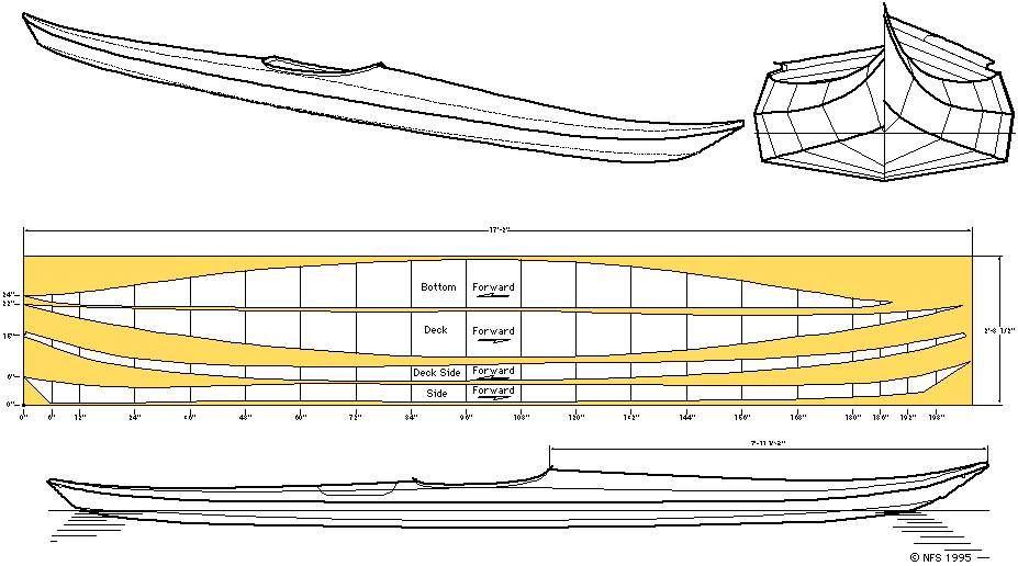
As you may have noticed, half of the parts are missing! This is because to plywood panels are pressed together, and cut at the same time, to obtain better precision.
There was a bit of confusion (my fault) about the tables - the seemed too far away from being a drawing to be usefull. Still, I didn't find any other way to represent these precision measures.
Anyway, below follows a description of the technique for passing the table information to the wood. (I'm not sure, but I believe Nick Schade has the drawing available in scale 1:1).
Ok, we'll use part of the second table as an example (that's the one I used):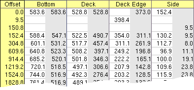 To pass this table to your plywood, use the following steps:
More than likely, the parts were glued together, but the alignment was not entirely perfect. To obtain a valid reference, it's necessary to draw a line along one of the large borders, which will be used as a reference in the next step. Draw this line near (a few mm) the border, but, of course, completely on the wood.
 I used a string to get a straight line, then marked this line on
the panel. This line is important!
I used a string to get a straight line, then marked this line on
the panel. This line is important!
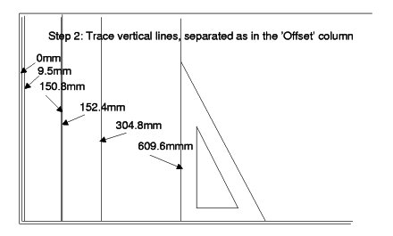
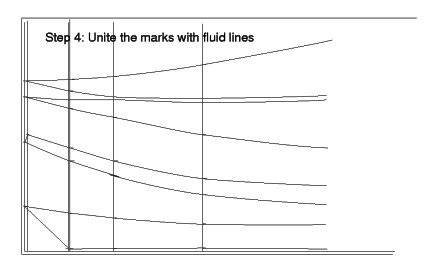
Draw a first vertical, as near as possible to the left border. From there on, draw other verticals at 9.5mm, 150.8mm, etc. (All the values that appear in the left - yellow - column of the table).
The first line (0.0 in the left column) has values like: 583.6, 583.6, 528.8, 528.8, 373.0, and 152.4. Make marks on the vertical at these distances. Of course you don't have to mark 583.6mm twice!
The second vertical, at 9.5mm, has only one mark, at 398.4mm. That's ok, some of the parts are shorter... Make the mark, and pass on to the next vertical. The third vertical has only one mark, at 9.5mm from the reference.
Get the idea?
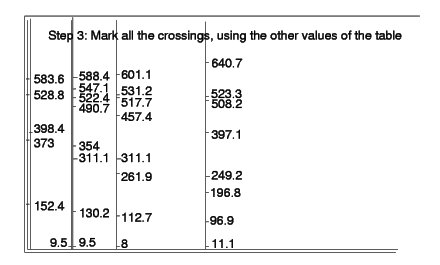
If a mark is really out of the way, check the table! (It happened to me)
| (c) John Coppens ON6JC/LW3HAZ |