A small calibration beacon
One of the steps to overcome during calibration of the chirp
reception is the measurement of the delays in the system. Basically,
there are two delays to take into account:
- The delay from the antenna input to the audio output of the
receiver. This delay is typically in the order of a few milliseconds.
To measure the delay, we need a transmitter which has either a
known delay, or a negible one (see below).
- The delay from the audio to the detection of the chirp in the
DSP. This delay is fixed, but may vary between different versions
of the EVMchirp firmware, as it depends on the algorithms implemented.
The measurement can be done with a simple jumper cable.
A simple chirp transmitter
|
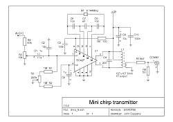
Using a simple crystal oscillator, and a modulater, it's possible to
build a transmitter in little time. Almost any crystal can be used -
the main delays in the receiver are in its crystal filters, so the
band on which the delay is measured is of little importance.
Looking aroung the junk box, I found an S042P, which is a simple
balanced modulator, which can also be made to oscillate with a crystal -
almost a complete DSB (double sideband) transmitter in one chip!
Note: R1, R2 and R3 (used to balance the modulator more precisely) are
not really necessary.
The circuit is also available as a PDF document.
|

|
Construction

|
As the frequency is low, construction is very uncritical. You could
probably even do a quick construction on a protobaord. I choose
perfboard.
 |

|
A view of the 'cabling' which suggests that a PC board would be
easy to design. The many white speckles are caused by the reflection
of the (too-near) flash.
 |

|
An image with 'normal' artificial light.
 |

|
... at a slightly different angle.
 |
14893
|
(c) John Coppens ON6JC/LW3HAZ |
mail |


