
Language:
Español
Reception:
QFH Antenna
Preamplifier
Original version
Converter
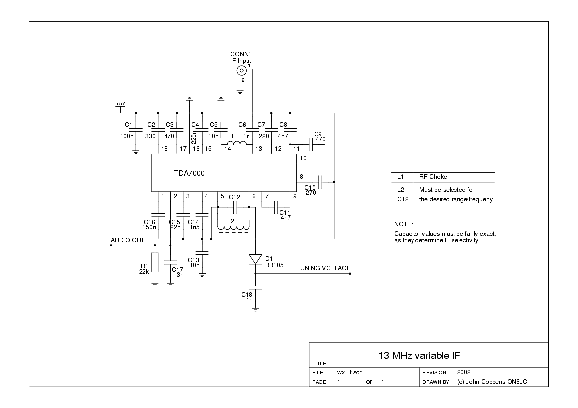
TDA7000 IF amp
'New' receiver
Other information:
Links
Legend
Archive
Bibliography
Wallpapers
Where are we?


|
Connections to the board
|

|
|
|
A better view of the board |
|||
The main motive of the mods was not that the circuit didn't work right, but were several tries to add some kind of frequency indicator to the receiver. The left RCA plug and associated components are witnesses to the last version, adding a FET buffer amplifiera and taking signal from the oscillator coil.
None of the indicator systems was satisfactory, and the actual stability of the receiver oscillator was so good that it wasn't really necessary either. A simple system with a preset resistor for each of the the desired satellites was more than enough, a simple selector switch to select the channel.

|
The oscillator section of the TDA7000. The inductor is a small
Amidon toroid - the smallest they had (8mm?), gray code. Almost any
inductor can be substituted, as long as it resonates at the desired
frequency. To the left (the small gray block with green spot) is the
BB105 varicap. The two turns of blue wire go to a FET amplifier in
an attempt to connect an external frequency meter
|
|
|
|

|
|
|
View towards the inputs and outputs (pwer and control).
|
||

|
|
|
|
The 'circuit board' side, witness of the age of this experiment
(about 25 years!). The traces are formed by cutting away the copper
with a small hand drill. The 47 pF capacitor is C12.
|
||
|
The diagram of the TDA7000 IF. It's also available in PDF format for those who
can't see PNG images yet.
I've also posted the TDA7000 datasheet, for which I had several requests. |
| (c) John Coppens ON6JC/LW3HAZ |